Sunday, January 31, 2010

You Win Some - You Lose Some ...

I love those Hepworth fittings!
After connecting the water pump and arranging for the drainage to go into a bucket from which the pump temporarily drew its' supply I opened all the taps so that if there were going to be any leaks they would be relatively small. While the taps are "on" there is not a lot of pressure in the pipes as all the water goes straight through. I could then go around and check each fitting for leaks without any flooding occurring at full flow. Not a single leak! Mind you the fittings are designed to withstand full mains pressure and all these caravan systems operate at about 25% of that. After the first check I could then gradually close each tap to let the pressure build up gently. As there is only the shower, kitchen sink and bathroom hand basin it's not too hard. Still no leaks! I love those Hepworth fittings!
Of course "sods law" has to get involved however . . .
Most of the 12Vdc water pumps are capable of delivering about 12litres per minute (lpm). Quite a few comments are made about how weak a flow this is. While looking to order my pump (on the net) I noticed that pumps of about 25lpm cost very little more. Why not have a more powerful pump and better flow? The answer to that question became very obvious very quickly. While the mains can force more water through because of the pressure these pumps are what are called "demand flow". ie They pump until the pressure builds up to a set point, about 25% mains, and then they switch off! When the tap is turned on the pressure drops and the pump begins pumping again until the tap is turned off etc. etc. Well it appears that my BIG pump can build up enough pressure to turn itself off even while the tap is turned on to its' maximum in about 1 sec. flat!! So it turns itself off - for about the 1 sec. it takes for the pressure to drop again - so it turns itself on again - etc. etc. etc.
As showers and many taps are now limited to about 9lpm it would appear that a pump of 10-12 lpm is ideal when only one tap at a time is turned - the norm for motor homes I would imagine.
I think I m going to have to experiment with an air chamber in the line to try and prevent the pump from switching itself to death in a very short time.

Never the less the shower, hand basin, sink and toilet have all now been "christened" and with the addition of a proper shower curtain proved necessary the plumbing is usable. If I drank a glass of champagne would be in order!

Time for a little clean up so some upholstery can be decided on for seating cushions.


It seems about time to start finishing a few things off so a door frame and door to the bathroom would be a nice touch. A length of beech timber is machined to be a nice fit around the edge of the door opening on each side.


These are notched out at the top


for a cross piece to be fitted and we have what starts to look like a door frame. This will be pulled out and coated with clear lacquer before being finally reassembled and stops fitted for the door to close against.
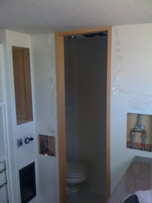


So now we know the final size of the opening a door can be framed up and then covered with some 3mm thick MDF


before being put in the "press", which consists of being underneath a big stack of sheets of plywood. Crude but effective. When dry it will be pulled out trimmed to size and lacquered white to match he rest of the cupboard doors.


A friend of mine has been telling me about a new 4x4 track which has been opened to the public near Dwellingup about an hour south of Perth. It follows along a creek with a few nice camping spots I have been told and shouldn't be any problem with clearance for my truck. In this map the green track is gravel while the purple and yellow are bitumen.


So I decided to take a day off and take my motorbike down and check out what it would be like for an exploratory trip. The entry to the gravel portion looked very promising . . .


But about 10km in it turned out like



with lots of overhanging branches and even deeper cuts between high walls. The ruts etc. would not be a problem by themselves but they were very sloped to one side with high walls which would make it too much of a risk of serious damage if the truck were to slip off to one side.
I am going to have to take my friend for a drive so he can see just how big a 12 tonne truck really is!
But having started and it seemed a nice day for a ride I decided to do the whole 100km just for enjoyment. One of the main features were a couple of old trestle bridges now seriously falling apart.




Some of them are quite safe for pedestrians


but vehicular traffic and going near the edge are actively discouraged!


And seeing I managed to fall off and have my bike land on top of me only once I consider the day was well worth it!

Saturday, January 23, 2010

and Back Inside Again . . .

Actually with the temperatures being what they have been, around 40 deg. for a while, it is actually nicer inside the truck with the air conditioning on and the temp. around 24 deg. !!

Of course it has been plugged into shore power all this time so the batteries have been kept topped up regardless.

During the time I have been working inside I have observed that the inverter at irregular intervals stops believing in "shore power" and begins inverting from the batteries for about 1 minute and then goes back on the mains again as if nothing as happened!!

Of course no one has any idea why this is happening . . .
After thinking about it for a while and doing a few little tests I think it may have something to do with a relay in the air conditioner and the polling mechanism the inverter uses to determine if a load needs servicing.

Being one of these modern computer controlled devices it can all be tuned via a laptop with the right software, available from the Victron site, and a special USB converter, from the local distributor. As this device is also quite new in the market even the distributor is not fully up to speed and I observed them doing a little bit of learning on my time when first setting it up. Also I will need to know how to tune it over time as a usage pattern develops, so I downloaded and installed the software and obtained the USB device and plugged it all in.


All went well using the "virtual control panel" until I set a parameter, for which the heading was obscured by a poor graphic, and it turned out to be the OFF switch and now I can't turn it on again via the computer as every time I plug it in it thinks it should be turned off - and that's what it does!
I think I am going to have to eat "humble pie" and borrow a real control panel (or get a new USB adaptor) to be able to monitor it via the computer to see if my theory is correct.
Oh well ! You can't win them all ....

So in the mean while I have finished installing the 12Vdc distribution panel


and now we have some real lights. This one in the kitchen is the most powerful and consumes about 16 watts. The wiring is temporary until I have finished the kitchen wall which is waiting until I finish the bench which is waiting until I finish the plumbing which is etc. etc. etc. . . .


This one is in the "bureau desk" and uses about 12 watts ( the wiring is finished here).


The rest of the lighting will be installed when actual use in the field determines where it is needed.
And just to tidy up the controller for the bed was also installed in the 12Vdc distribution area and the operating switch was enclosed in a small grey plastic box obtained from Altronics the electronics store and positioned with velcro next to the battery controller.


Similarly the limit switches, one each for UP and DOWN, were also enclosed and placed with velcro, in this case temporarily, until the final heights are determined by things like table height and mattress thickness.


So some plumbing is now in order . . .
The drainage side needs to be finished first for obvious reasons and the hand basin and shower are the hold ups.

The first little thing to do was make a collar for the hand basin tap to just lift it up over the edge of the basin.


Now the drain for the basin needs to be finished. After much searching an "eureka" moment occurred when a piece of washing machine discharge hose was spied.


This was soft and pliable and the right size and near perfect except that the corrugations may hold some residue which may smell after a while. Unfortunately I can't put a "P" trap until after the hose so it may just get some chemical cleaner every now and then - I'm told "Dettol" works quite well! So a section was cut out and the fittings fitted.


Then attached to the basin


The end of this you may remember was made to swivel so that it could fit into the confined space under the basin which slides in and out.
This fitting comes out into the space just above the water heater which is the earliest point where a "P" trap can be fitted.
The now standard fabricated variety was constructed


and installed in the appropriate place and then a heavy duty pipe can be connected for the journey down to under the floor


where an elbow changes direction to cross to the other side


where it meets up with the rest of the drainage system going into the grey water tank with the shower and sink and external drain outlet.


The sink was described earlier so only the shower needed to be done. I hesitate to use the "only" word here as the shower base uses a household plumbing fixture 50mm in diam. which needs to connect to the 25mm diam. used in the rest of the system and turn through a right angle all the while using a minimum of vertical space.
Off to the local plumbing shop for about the 50th time . . .
A collection of fittings was amassed which could with a little bit of machining to adjust a few sizes


be assembled into a single fitting to achieve this end . . .


You can just see it in position in an earlier photo of the combined outlets.

So now all the discharge was connected a few buckets of water in each basin and the shower were in order to see if everything works. The sink is very disappointing in terms of the speed of draining but that is due mostly to the silly little outlet sieve to stop large pieces going down the drain, the hand basin is a little better and the shower is best of all.

The following morning revealed only one small leak at the entry to the grey water tank where I had not done a fitting up tightly which was quickly rectified and all looks promising so far.

Next the inlet side needs to be tidied up and a proper system test can be undertaken . . .

Sunday, January 17, 2010

The Stuff Outside . . .

More electrics . . .
Time to hook up the charging circuit from the truck.
I originally thought that I would be running cables from the alternator or something but of course they are already there . . . as far as the truck battery anyway.
So all I need to do is pick off the +ve and -ve from the battery bank on the chassis.
So the heavy duty cables are run up into the house through a couple of waterproof glands fitted to a plate covering the horrible hole left over from earlier temporary cables.


Which went something like - make the original hole bigger


screw the plate up from underneath with a couple of holes for the glands


The third hole is for reversing camera and body clearance light cables.
Seal it up with a little bit of paint


Poke the cables through the glands and push the big grey Anderson plug together. These are special plugs designed to carry heavy DC currents. This one is rated at 125 amps. The plug is there of course for when the body has to be taken off the chassis (which will have to happen once or twice more for final sealing and new springs).


The other pieces in the cable are an 125amp fuse and a voltage sensitive controller which disconnects the starting batteries from the house batteries until the starting batteries are fully charged and then the surplus goes to the house batteries. At the moment the truck alternator is only rated for 40 amps but the system has been designed so that it can be doubled in output to 80 amps. That is just enough to run the air conditioner so with the added 10 amps from the solar panels (in theory) it is enough to air condition the house while travelling without using the batteries at all! At the moment with every thing topped up it will deliver about 36 amps to the batteries. Interestingly enough the voltage isolator setting is slightly less than the house battery voltage when fully charged and the truck batteries are slightly older and less effective than the house batteries so when you stop the house batteries reverse charge the truck batteries until they reach the isolator setting when it all disconnects. In practice that prevents the house batteries from being able to rest fully charged unless I turn the truck batteries off manually (there is a switch to do that) but it does reinforce the theory that all batteries should be of the same age and use pattern in the one installation so they don't all get dragged down to the weakest battery.

It just occurred to me that as the truck is again going to the electrical installers tomorrow I had better restrain the fridge temporarily as it is now sitting on lovely smooth sliders and will try and destroy them as I am driving tomorrow.
The simplest way is to screw a couple of these weirdly named "breeching staples" into the back wall and run a strap through them


with a simple clip in the front and it actually works quite well . . .


it might be a while before it gets replaced with something more sophisticated . . .

Saturday, January 16, 2010

The Heat of Battle . . .

With the temperature in the 40 deg. range for a couple of days it seemed prudent to hook up the shore power, turn on the air-con and do a couple of little jobs in the cool.

Organising the 24Vdc had me a little concerned to begin with. The plug and cable supplied with the fridge is marked as 12/24v but there is a big sticker on it saying "12V only"!


This is because here is a little green diode on it which lights up when there is power connected and inside it is a special fuse which does not work properly with 24v!


Now IMHO they should also supply an alternative fuse for 24v connection - but that would still not prevent the diode from burning out. It really is only the size of a little resistor inside there somewhere which needs to be different from one voltage to another. Surely a little switch and extra resistor could be incorporated for about 5c!
An additional concern is the socket into which the plug goes. These plugs are intended for auxiliary power sockets in cars etc. - the problem with these is that they are not designed for anything other than a hole in a piece of sheet metal! The style of plug and socket for DC components in other installations is quite different and would mean cutting the plug off the cable
and using something else - which of course means you can't then use it in a car again without getting another cable "just in case" - about $50 !!
So I decided to pay a visit to the local "12V Shop" specialists to see if anything else was available.

We can live in hope can't we???
Lo and behold - secrets are revealed !!!
It appears that the plug is actually two plugs . . . one screwed into the back of the other.


And not only that but there is a nice wall mount fitting into which the hidden plug can now be screwed to ensure it doesn't fall out with vibration. And if you want to use it in the car again you just need to screw the original top back on. Things just keep getting better and better . . . there has to be a catch somewhere . . .


And of course there is . . .
In all this low voltage DC wiring you need to use very heavy wiring to prevent resistance, heat, voltage drop etc. etc. etc....
So of course on the back of the socket are the two smallest - stupidist - useless connectors imaginable. How the hell are you supposed to make a decent connection to them??


It would appear "only with the greatest of difficulty" . . . fortunately the material for the socket is fairly heat resistant so about 30 minutes of contortion in the cupboard with a soldering iron finally sees the installation done. You will also notice the addition of a 240Vac socket "just in case something goes wrong".


I still needed to make sure the fridge did not fall off the sliding platform on which it will be mounted.
First step is to attach the "cups" for the feet. At the same time a "riv-nut" was inserted into the frame


and a hook screwed into it.


Some brackets were attached to the fridge where the handles would normally go and turnbuckles fitted into them.


The fridge is then loaded on and the turnbuckles tightened into place


I don't think that's going too far !!
While down in the corner it seemed a good idea to put a couple of labels on the 24Vdc panel.


Thank you Mr Dymo.

A bench top 240Vac socket (GPO) is handy for several cooking appliances, but apparently they must be a minimum distance from the sink ( I don't know what that distance is ) but right up in the corner is about as far away as I can get and still be useful so that's where it's going!


Of course all outlets in motorhomes etc. must be "double pole" (which means that both active and neutral wires are switched - normal switches only operate on the active wire) read "costs twice as much"!


So re-route the cable previously tucked out of the way and screw it all into the selected spot.


One of the things left to test is the generator input so an appropriate cable and junction box needs to be installed so he generator can be plugged in.


This has been an interesting point of contention with the system suppliers and myself. The system has the capability to make use of and provide quite substantial amounts of power which has meant some pretty heavy duty wiring here and there. Similarly the generator has the ability to produce substantial power - about 23amps max.. Normal extension cables and power outlets are rated at 10 amps so the generator has three outlets on the front panel (which are rated to the next size up at 15amps each). All this means that if you turn everything on and have flat batteries the system can deal with it all quickly. Provided that the cables etc can carry the power. So the suppliers want to cater for the maximum disaster possible and install cables and plugs etc capable of 20amps plus. My argument is that if you ever get in that position - something has gone wrong!! So much to their disgust I have said to put in a single 15amp connection from the generator and program the system not to draw more than that. If it doesn't work out it will only need the connections upgraded and reprogramming - I can live with that.
Similarly the system can detect whenever the batteries get low and or I am using considerable power and can start the generator automatically. This is fine for a fixed installation, like a remote farm house, but I am not sure it's appropriate for a 4WD truck lurching along a bush track. For a start you would need to leave the ignition and fuel switched on while travelling. This is not a good idea . . . normally you turn everything off while travelling . . . imagine a water pipe breaking and the pump sees that as a tap turned on and proceeds to empty your water tank onto the floor.
So again in spite of "not realising the full potential of the system" I have diverted the automatic start signal to just light up a diode to say "start the generator".
So cable, diode, resistor and heat shrink


assembled ready for installation.


The best place to put it seemed to be in the control panel mounting box so the next job was to get that installed. So mount the box on the wall just above the switch panel.


Drill a hole and pull the cables through


And fit the front panel and the diode in the top left corner


Now I think I have to go outside and do some stuff there and the temperature hasn't gone down any that I can feel . . . .